CFD Case Study – First Community Church
Project: First Community Church North Campus
Location: Columbus, OH
Building occupants require a consistent environment to achieve their optimal level of comfort and the HVAC Systems are the main driving force in keeping any environment properly conditioned and ventilated. Especially in a church, proper ventilation and temperature are key in maintaining comfort.
Background
First Community Church (FCC North) needed guidance and clarity on where to place destratification fans for the best cooling for churchgoers while also keeping in mind a pipe organ and its occupant. Room temperature, not being a scientific term, is often coined at 70 ˚F which is the temperature where most people are comfortable. The goal was to have the heat rise while having a proper flow of air allowing churchgoers to enjoy a room temperature environment.
Korda/Nemeth Engineering was asked to complete a diagnosis and provide expert recommendations on the placement of destratification fans while taking elements such as diffusers, registers, and returns into consideration.
Computational Fluid Dynamics (CFD)
The Korda/Nemeth Engineering team used computational fluid dynamics (CFD) to evaluate two different scenarios. CFD uses numerical analysis and algorithms to solve fluid flow situations. In this case, the air was the fluid. The two cases were run under a cooling scenario, the same temperature, diffuser layout, and the same relative humidity. The program also used various inputs such as inlet and outlet boundaries, wall boundaries (occupants, fans, equipment, lights, solar), and thermal properties of structures such as exterior walls, roof, and glass windows. Some minor assumptions were added to the model such as steady-state conditions, the same air temperature, and moisture content in the air. Case 2 was run with 3 destratification fans with heights and distances given by the contractor. Case 1 was run with an absence of the destratification fans in order to better compare both scenarios. The scenarios where both ran using the same geometry coming from a model. (Figure 1)
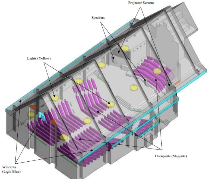
Figure 1: Geometry of the Church View 1 – Case 2 & 3
The parameters used to gauge temperature and comfort were temperature gradient graphs and the predicted mean vote (PMV) chart. PMV is an index that defines the average thermal sensation of a large group of people based on the American Society of Heating, Refrigerating, and Air-Conditioning Engineers (ASHRAE) seven-point thermal sensation scale. This index combines numerous environmental conditions such as temperature, humidity, air velocity, and mean radiant temperature with human factors such as clothing level and metabolic output to create a single comfort parameter. You can also see ventilation effectiveness (Ve) used in the study based on the Age of Air (AoA). This value simply states that the effectiveness of said ventilation method based off an acceptable indoor air quality.
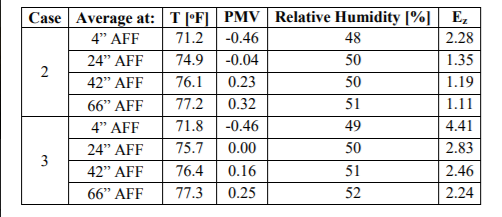
Figure 2: Area Averages for Variables
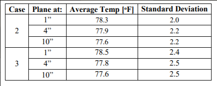
Figure 3: Standard Deviation of Temperature at different locations in front of the organ
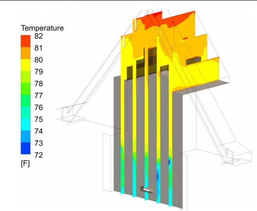
Figure 4: Temperature Contour Along Face of Organ – Case 2
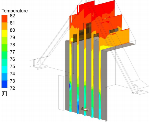
Figure 5: Temperature Contour Along Face of Organ – Case 3
As you can see in the above figures, the temperature gradient along the face of the organ is cooler with the addition of the fans. The same temperature gradient applies to the whole church structure.
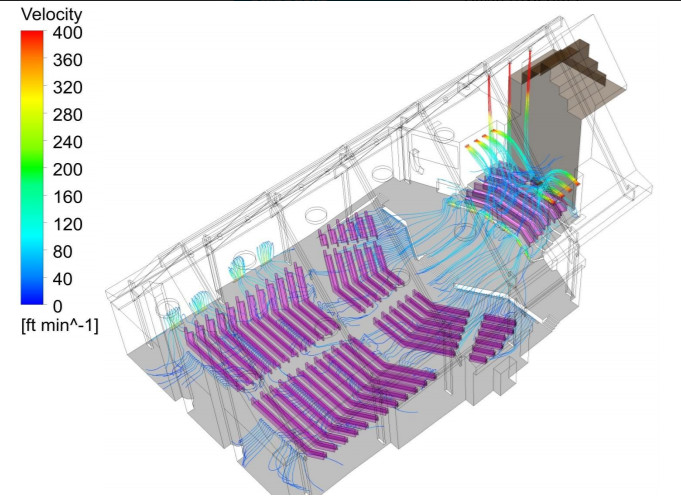
Figure 6: Velocity Streamline – Case 2
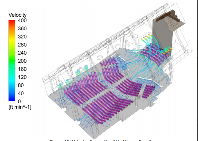
Figure 7: Velocity Streamline – Case 3
As seen by comparing the figures above, the addition of the vans provides more uniform velocity streamlines along the floor of the church.
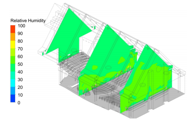
Figure 8: Relative Humidity Contour – Case 2
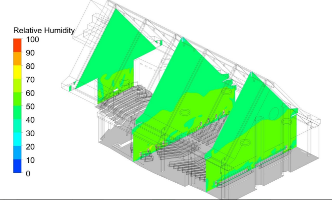
Figure 9: Relative Humidity Contour – Case 3
As seen above, the fans did not change much in terms of relative humidity as relative humidity is the amount of water vapor present. The addition of fans would not affect such values.
Based on the figures above, the Korda/Nemeth Engineering team was able to provide expert knowledge. Although both cases do provide comparable occupant comfort, Case 2 has a more uniform temperature distribution close to the organ (As seen by comparing Figure 4 & 5). It is also noted that the current air distribution system will limit the temperature uniformity near the organ pipe based off the double deflection grilles providing cool air from the mid to lower section of said organ. The experts at Korda/Nemeth Engineering also recommended increasing the throw of the destratification fans to reduce temperature difference near the organ at the expense of the occupant confront in front of the organ. Another recommendation is to orient the destratification fans to be the same distance from the organ pipe to provide uniform coverage of air along the organ pipe’s face.
Conclusion
The Korda/Nemeth Engineering team was able to perform CFD for the proper placement of destratification fans at First Community Church. As a result, the team was able to recommend proper placement of the fans to ensure that both temperature and airflow were optimal for churchgoers and the person operating the pipe organ. Based on the PMV and the graphs, it is established that both cases meet the needs of occupant comfort. However, the results did lean towards Case 2 as it had a more favorable temperature distribution closer to the pipe organ.
With this being an air flow HVAC system challenge, the Korda/Nemeth Engineering team was able to deliver a design solution and offer expertise with proper CFD analysis that took into account factors such as temperature, humidity, people’s heat output and skin temperature, location of fans and other HVAC elements, and U-values of boundaries of the structure to provide a solid CFD model.
Korda/Nemeth Engineers are equipped for any CFD analysis. From office and commercial buildings to educational and government buildings to healthcare and acoustic-sensitive environments, Korda/Nemeth can deliver innovative solutions for your HVAC and architectural product needs. Contact Korda/Nemeth Engineering to speak with a CFD expert today.